The length of the centre resonator that was too long has been trimmed and the cavity flipped upside-down in order to solder the top end plate in place. I later found out that I had to remove the upper lid again since I apparently had produced a short circuit at one of the inner hairpin couplers while soldering it in place

Since
the whole cavity filter is made out of copper, the tubes were conducting the heat so well - the bottom joints were melting (meaning solder running down inside the cavities). I had to remove a lot of excess solder and redo the bottom joints once the metal cooled.


Now, gently move the humps so that the power level has its maximum at the centre. This may take some time and it's a good idea to bring some patience.
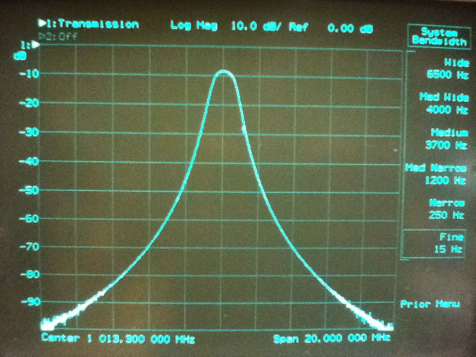

A first glance at the 3 dB bandwidth: 1.10 MHz with an insertion loss of 8.50 dB. Since the loss is rather high and the filter skirts steep, I would assume the cavities being under-coupled. I tried to have the hairpins very close to the cavity walls so that less energy is coupled.

.

The group delay is not as good as when the cavity was critically coupled but still much better than if it was over-coupled. It apparently makes the filter a little easier to tune as the elements interact less than at over-coupling. The resulting slightly higher loss is not a big problem in the spectrum analyser but it may be in low noise receivers.

The shape factor is equal to the 60 dB bandwidth divided by the 3 dB bandwidth, i.e. 7.76 MHz / 1.1 MHz = 7.05 which is really really good. Shape factors of 11 are very common and it may get as low as 3-4 with digital filters.
My filter is ready and the results are:
Centre frequency: 1013.3 MHz
Insertion loss: -8.57 dB
Bandwidth(3 dB): 1.10 MHz
Bandwidth(6 dB): not tested
Bandwidth(30 dB): 3.25 MHz
Bandwidth(60 dB): 7.76 MHz
Shape factor: 7.05
Rejection(1024 MHz): 95.4 dB
Rejection(1034.7 MHz): -105.4 dB
No comments:
Post a Comment