Pages

Tuesday 29 November 2011

More components arriving

Excellent! I got my feed-through capacitors on Monday and the VCO kit from Mini-Circuits. Additionally, I'll have the day off on Wednesday so there's lots of time to grab the solder iron and errr...write some reports! I just realised that I still have work to do.

Anyhow, these are super cheap Russian 100 pF feed-through capacitors. The date code on them suggests that they were manufactured in 1984. They're in excellent shape though and the one I measured was spot on. I'll use them to prevent the RF energy from escaping my prototype aluminium enclosures, since I have to get the DC power lines in there similar to how it's done in the next picture:

This is one of BG6KHC's aluminium enclosures. The leads you can see on the left side are feed-through capacitors that connect to the power lines and the serial interface of the 16-bit ADC inside. I like the ruggedness of this type of enclosure and intend to use a similar approach for my prototype modules.

For anyone who is looking at building Scotty's Spectrum Analyser and lives in Europe: the kit that contains all the necessary parts from Mini-Circuits is now available from Mini-Circuits Europe and I'd recommend you to contact one of their account managers for a quote. Their service is splendid and it took less than a week before I had the parts arrive at my office.

The kit contains:
  • 1x ROS-1500+ 
  • 2x ROS-2150VW+
  • 1x TC16-161TG2+ 
  • 4x ADE-11X+ 
  • 10x ERA-33SM+

Friday 25 November 2011

SMA Connectors

I received the SMA connectors from Hong Kong today and a couple of SMA male to SMA male RG316 cables. Shipping was relatively fast this time - only about 24 days.
The price for one cable was cheaper than the price for two connectors plus cable, so there is really no point in making them myself. Besides, these are just for testing purpose since I did not want to waste my hard pipe and semi-rigid cable for this.

The gold plating of the connectors does not have the same "feel" to it like good quality connectors from for example Suhner or Amphenol, but considering a price ratio of 1 to 8 and given the fact that I will not remove the connections once everything is installed, I guess I can live with it.

Thursday 24 November 2011

Resolution Bandwidth Filter #5

I found a screenshot that I took during the prototype test. It resembles the frequency response of the NDK 10F15DG after successfully tuning the matching circuit.

Really nice ripple of approximately 0.4 dB and the insertion loss is low too with only -2.4 dB. The picture actually states a loss of -7.9 dB but the input power was -5.5 dB.

The matching circuit was 3.3 uH in series and 10 pF + 5...25 pF trimmer in parallel,  if I remember correctly:

I recorded the 2-port touchstone data for this filter with 1600 points. You can download it as a zip file from my Google docs: NDK10F15DG_plain.zip

Sunday 20 November 2011

Input Switch

Slowly getting there.

This is the input switch of the network analyser. Its purpose is to switch between transmission/reflection measurement and it also provides a switch to choose between spectrum analyser (SA) and vector network analyser mode (VNA).

I decided to mount the SMA connectors in the same style as I did with the other modules instead of letting them protrude from the front panel.

I use 0.2 mm (50 mil) copper sheet for the  perimeter fence. It requires a bit of practise but I found that using one single strip works better than joining two brackets. I used a pair of scissors to cut the sheet.

 Internal shielding. It requires a lot of patience to install the fences. Some of them are made of double sided copper-clad FR4 in order to keep ground planes separate.

 Almost finished. I need to seal the individual sections with copper lids as soon as I get my hand on the missing capacitors. You can see the RF-relay that switches between VNA and SA mode in the lower left corner.

Bottom view. A few power supply jumpers are missing. The three SMA connectors on the top are for the  transmission, reflection and spectrum analyser inputs, the SMA connector to the left below them is the selection output. The semi-rigid coax jumper on the bottom connects two sections.

The thing needs a box!

I've been searching for a nice enclosure and it's really hard to find something nice. I was thinking of some kind of CNC-milled aluminium frame but since I still relocate modules every now so often I will postpone that decision until I actually finish all the modules.

For now, I will use a simple box made of FR4 and mount the modules on a PCB frame.


 The box is made of FR4. I took two 200x300 mm single-sided sheets and cut them into half. The width of the box on the inside is exactly the width of a DIN A4 sheet.

The bottom of the box is double sided FR4.

The sides are simply soldered together. I will use this to shield the finished device.

 Not pretty but extremely practical and cheap.

This is the FR4 frame on which I will mount the individual modules. Its dimensions are exactly the same as the bottom of the box.

I've been peeking to the left and right at what other people are doing. All of my SLIM modules have a 0.08" copper strip perimeter fence on the outside of the PCB that connects top and bottom ground. The milled holes in my base plate are exactly the size of a SLIM, i.e. 1.2" x 1.2" etc. That way I can place the shielded SLIMs on top of the base plate and tack them in place.

Resolution Bandwidth Filter #4

The fourth RBW filter. I'm beginning to like the smaller cans, this one is a Hy-Q10726 which is a 8-pole bandpass with a bandwidth of 7.5 kHz and a centre frequency of 10.7 MHz.

There's really not much to it. The filter can, two connectors, the PCB and matching components.

Long version SMA connectors.

The innards. I think I matched this particular filter with 5.6 µH and 33 pF + a 6...40 pF trimmer. Note how the input and output section is shielded with a fence in the middle of the board.

Update: Managed to take a picture. Ripple could be better. I also recorded the 2-port touchstone data for this filter with 1600 points. You can download it as a zip file from my Google docs: Hy-Q10726_matched.zip


More perimeter fence. Getting good at this :)

Direct Digital Synthesiser (DDS 1 and 3)

These are the synthesisers that steer the phase locked oscillators. Their heart consists of an AD9850 which is a 125 MHz complete CMOS DDS from Analog Devices.

The DDS 1 Module, SLIM-DDS-107, is the fine frequency "steering" source for PLO 1 in the MSA.

 Finished DDS1. There's not much in there, you can see a 78L05 voltage regulator to the left, the AD9850 itself in the centre and a 10.7 MHz crystal filter to the right.

The filter is shielded from the rest of the circuit with a fence.

Bottom view. The SMA connectors are not placed yet as they weren't in the mail. Connectors in China are incredibly cheap but you have to live with up to 30 days of shipping...

 Both synthesisers and a couple of extra perimeter shields.

A few copper strips prepared for the shields

The first few attempts were crap but his frame is actually almost a perfect fit. I'm bending the strips with small pieces of PCB.

Current status

I've completed another set of boards this weekend. The new PCBs are really small and the quality is alright. The complete lack of solder mask and silk screen can be annoying at times.

Boards that are fully populated at the moment are:
The Control Board, the four Mixers, the two DDS boards, the 64 MHz Master Oscillator, log detector, AD converter unit, Phase Detector and the Filter Bank Selector.

Boards missing so far:
The three Phase Locked Oscillators, I.F. amplifier.

Note to self: place an order for the VCO chips at Mini-Circuits.

New set of PCBs

An RF-engineer from the USA was kind enough to provide me with a full set of boards for the Vector Network Analyser project. This way I don't have to send an order to ExpressPCB who otherwise offer an excellent service. The shipping costs to Europe is a is $67.00 for a 2-3 day courier, which is the only shipping option their software let me choose.

This is what the PCBs look like when you order their standard service 2-layered boards. The cost for two of these panel is around $100 and the cost for 10 panels is $333. I highly recommend you to organise a group buy or simply buy 10 panels yourself and ask if anyone needs one. New people join every month and face the same problem of how to acquire the boards.

From the top left to the bottom: two PCBs for crystal ladder IF filters, ADC PCB for chip packages with 8 leads and the resolution bandwidth filter bank switch.

On a side note: with enough people for a group buy, you may as well order ROHS silver PCBs with silk screen and solder mask. The lack of solder mask can be a bit annoying at times.

Resolution Bandwidth Filter #3

Another filter update. I acquired a couple of monolithic crystal filters with the smaller D-151-D multi-pole package that fits the 1 x 1 SLIM modules. Most of the filters were manufactured by NDK with the exception of a single Hy-Q10726.

They are all 8-pole filters but their centre frequency varies. I now have

NDK 10F15DG:
has a centre frequency 10.7 MHz and a 6 dB bandwidth of 15 kHz

NDK 11F30D:
has a centre frequency of 11.5 MHz and a 6 dB bandwidth of 30 kHz

NDK 11A1.0C:
has a centre frequency of 11.4 MHz and a ? dB bandwidth of 1 kHz

Hy-Q 10726:
has a centre frequency of 10.7 MHz and a 3 dB bandwidth of 7.5 kHz

This is the NDK 11F30D. I managed to tune it and save a two port touchstone file but the data is still in the memory of the network analyser in the uni. It took me two diskettes to figure out that the floppy drive is broken. I'll have to repair it at some point.

Took a shot with my iPod, best I can do at the moment. I'm not too happy with the ripple.

Update: I recorded the 2-port touchstone data for this filter with 1600 points. You can download it as a zip file from my Google docs: NDK11F30D_matched.zip

Resolution Bandwidth Filter #2

Despite the broken milling machine, I managed to finish two PCBs for the bigger NDK crystal filters I have. Their footprint is huge mainly due to the integrated transformers. This particular filter is an 8-pole 10.7 MHz with a 3 dB bandwidth of 7 kHz.
  
 I used double-sided copper clad FR4 for the fences. It oxidises really fast so I'd recommend tinning it before you attach the strips on the PCB.

The physical dimensions of the board is 1.2 x 2.4 inches, which translates into a 1 x 2 size SLIM. Although these filters function very well I think I prefer the ones with a smaller footprint.

 Bottom view, ready to have the matching circuit placed. I was recommended to solder the bottom of the crystal can to the top copper plane for shielding purposes. I fear however, it may melt some of the connections inside since the metal can soaks a lot of heat. Instead, I used adhesive copper tape and soldered it to the PCB.

The matching circuit of this particular filter consists of (I think to remember) a 1.8 uH and a 2.2 uH inductor in series, and a 10 pF in parallel with a 6...30 pF trimmer.

I don't have anything but copper tape at the moment to serve as a lid. It should work just fine. I should try to get my hands on some copper or brass sheet but it's another thing that seems difficult to obtain here in Helsinki.

The SMA connectors are mounted and the in and output labelled. This filter is ready for tuning.

I have a printout of the amplitude response of the tuned filter somewhere. I should add it here once I find it.


Picture taken with my iPod. The ripple is quite nice.

I recorded the 2-port touchstone data for this filter with 1600 points. You can download it as a zip file from my Google docs: NDK10P7D_plain.zip

Resolution Bandwidth Filter #1

I acquired a couple of cheap 8-pole NDK 10P17D and 10P7D crystal filters which I intend to use as RBW filters. I don't know the actual specifications other than that they all have a centre frequency of 10.7 MHz. Their bandwidth is supposedly 17 kHz and 7 kHz.

I don't have any ready made PCBs for these filters at the moment as it turned out that their footprint is rather large and won't fit on a 1 x 1 SLIM. The picture above shows a top view of the home-brew enclosure I came up with. I used scrap FR4 for the walls and shielding and soldered it together to form a very crude box.This prototype is simply a perfboard which I coated with copper tape to get some kind of ground plane. I forgot to take pictures from the inside - but it's really not that exciting anyway.

A preliminary test revealed that the in/out impedance suggested by the seller was way off. These filters appear to be matched already, but for 100 ohms. 

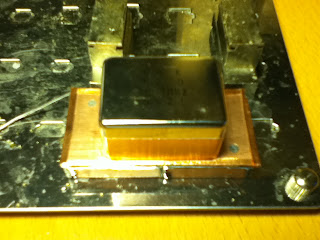
In this picture you can see how I used adhesive copper tape to seal the bottom of the filter.

After a long night of chasing data sheets I think I found something useful. Apparently the terminating impedance of this filter is 910 ohm/ 25 pF. On top of that these filters seem to have an integrated matching transformer.

I will design a proper PCB for this filter can type but for now this one has to do the trick.

This is a very hasty frequency response taken with a HP4395A to get a first idea of the filter properties.

Edit: I recorded the 2-port touchstone data for this filter with 1600 points. You can download it as a zip file from my Google docs: NDK10P17D_plain.zip

Coaxial Cavity Filter Episode 1

The cavity filter will tune from approximately 900 MHz to 1050 MHz and has a 3 dB bandwidth of about 2 MHz. Its purpose is to attenuate the fundamental (1024 MHz) and image frequency (1034.7 MHz) of local oscillator 2. For that purpose it will be tuned to 1013.3 MHz once it's ready. The rejection at 1034.7 MHz will hopefully be greater than -100 dB.

Mechanical drawing taken from http://scottyspectrumanalyzer.com/protocavfilt.gif
I have seen something similar in the RF laboratory of Motorola's product support engineering department back when I was an RF-technician apprentice. This cavity filter doesn't use the traditional rectangular shields with aperture coupling though, and it is somewhat difficult to find good information on the construction of such filters.

It turned out to be quite difficult to acquire copper tube here. Bauhaus was selling 3 m (10 feet) pieces of 28 mm (1  inch) diameter tube for 50 EUR, which I found rather unreasonable. After about two weeks of research I found a source in southern Germany that was able to provide me with the copper parts I needed for not even half of what Bauhaus was asking.

I have two options when it comes to the centre resonator. I either use solid copper pins and thread them in order to be able to tune the cavity, or to use 6 mm  (1/4 inch) hollow copper tube and implement brass tuning screws as seen in the mechanical drawing. I don't have any tapper here so I decided to go with tubes for the prototype.

I used a hand saw to cut the four cavity tubes. This was really a pain in the neck and I recommend anyone who tries to build this kind of filter to buy a pipe cutter. Otherwise, you will spend a considerable amount of time trying to file the tube ends so that they may be reasonably parallel once placed on the bottom plate.

Everything is polished with steel wool. The copper pins in front of the cavity bodies are actually pieces of RG-141 semi-rigid coax.

Drilling holes for the resonator pins was the easy part. I gave up trying to drill 1 mm holes for the hairpin couplers with a hand drill. I may point out that I use 5 mm copper flat bar since I was undecided whether to use threaded solid pins for the resonators or hollow pipes. I guess a 3 mm sheet would have done the trick too, with less hassle. If you have access to a drill press I absolutely recommend to use it.

The cavity bodies marked for drilling.